
|Articles|October 1, 2008
Dental radiography: Small improvements to technique can make a big difference
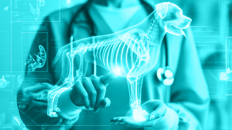
Veterinary dental radio-graphy traditionally has been one of the most frustrating aspects of veterinary dentistry.
Advertisement
Veterinary dental radio-graphy traditionally has been one of the most frustrating aspects of veterinary dentistry.
The bisecting-angle technique can be demanding and difficult to perform consistently. Positioning the patient, the sensor and the tube head to create quality images can be problematic, too. This article will provide some tips and techniques to help minimize common frustrations in veterinary dental radiography.
Parallel and bisecting-angle techniques
In traditional radiography, we commonly use the parallel technique to obtain images. For example, with a radial fracture, the limb is placed on the X-ray table. The tube head is positioned above the limb and pointed directly at it, and the film is tucked under the limb and parallel to the tube head.
When we take views of the teeth in the dog and the cat, we can use only parallel positioning in the mid to caudal mandible. This is possible only because the soft tissue (lateral to the tongue in this location) allows the sensor to be placed parallel to the caudal cheek teeth and mandible intra-orally (Photo 1).
Photo 1: The parallel technique can be accomplished only in the caudal to mid mandible in our companion-animal patients.
As we move rostral with our sensor, the mandibular symphysis gets in our way and prevents use of the parallel technique.
In the maxilla, the palate provides a similar barrier. Therefore, the tube head and sensor must be positioned in a way that will allow projection of the tooth image on the sensor that will give the same result as a parallel technique. The technique that allows us to accomplish this is called the bisecting-angle technique (Photo 2).
Photo 2: Demonstration of the bisecting-angle technique on a skull. The angle for canine tooth imaging in this patient is 70 degrees with a rostral to caudal oblique tube-head orientation.
Patient and sensor positioning
How do we position a companion-animal patient correctly to take veterinary dental radiographs? The answer lies in consistency.
In order to minimize the variables in the steps to follow, positioning should be approached the same way in each patient, depending on whether we are taking views of the mandibular arcade or the maxillary arcade.
Photo 3A: Wall-mount radiography unit demonstrating the location of the angle setting.
Sternal recumbency is preferred by this author for taking views of the maxillary arcade. The angle setting on the tube head of all dental radiography units is measured based on degrees from the horizontal plane (Photos 3A and 3B). So, if you use this valuable tool to help obtain consistent quality veterinary dental radiographs, the positioning recommendations described make perfect sense.
Photo 3B: Close-up of the angle setting.
In our example, the patient's head is elevated so that the palate is parallel to the table (Photo 4). The digital sensor is placed intraorally in an orientation parallel to the palate and the table.
Photo 4: Proper patient positioning for taking radiographs of the maxillary arcades.
For the same reasons, dorsal recumbency is preferred for obtaining mandibular images (Photo 5). With dorsal recumbency, the body of the mandible is positioned parallel to the table. The sensor again is placed parallel to the table in all but the caudal mandibular view where the parallel technique can be used.
Advertisement
Photo 5: Proper patient positioning for taking radiographs of the mandibular arcades.
Why so detailed?
If we control the variables involved with positioning the patient and the sensor, the only variables we must approach from this point is the position of the tube head and its angulation that is read off the unit as previously described.
In addition, each patient requires very similar tube-head positioning. The tube-head position and angulation for caudal cheek teeth in a small dog and that of a large dog are very similar.
Once you get used to taking that view in any dog, you will become familiar with the approximate position and angulation of the tube head. You should be able to consistently reproduce it in future patients.
If the patient and/or the sensor are positioned a different way each time, then the tube-head angle and position suddenly become confusing variables.
Tube-head angulation and position
With dog and sensor positioning controlled, the tube head should be set at an angle of 45 to 70 degrees to produce an image that is reasonably close to a similar image taken if parallel technique were possible (Photo 6).
Photo 6: An example of the caudal-to-rostral oblique view for imaging the caudal maxillary cheek teeth in the dog. The tube-head angle is 55 degrees.
In the cat, the same is true except for the caudal maxilla. Angle settings should approximate 30 to 40 degrees for an intraoral view in the cat. This is to avoid superimposition of the zygo-matic arch over the image. Slight elongation of the caudal cheek teeth occurs due to this narrow angle.
Tube-head positioning falls into four general categories:
» parallel
» caudal to rostral oblique
» rostral to caudal oblique
» lateral
Table 1 offers more guidelines.
Table 1: Recommended tube head position for dog and cat
Sensor-positioning aids
Various devices can be used to help position the digital sensor within the mouth so that it stays in the desired position. Gauze, paper towels, flexible hair curlers and other positioning aids can be used. The author makes custom foam wedges by cutting blocks slightly larger that the sensor and then using scissors to create a slot to place the sensor. This allows positioning for the premolars and incisors in the dog and protects the sensor in case it is dropped. Paper towels are folded in various shapes and wrapped to produce positioning devices and gags (Photo 7).
Photo 7: An example of the caudal-to-rostral oblique view for imaging the caudal maxillary cheek teeth in the dog. The tube-head angle is 55 degrees.
Increasing the friction of the sensor against the oral cavity helps decrease sliding of the sensor once it is properly positioned. An inexpensive way to accomplish this is to snip the finger out of an exam glove and place it over the sensor. This replaces the slick inserts that are provided with the sensor kit.
It is important to practice taking dental radiographs on a skull to obtain reasonable proficiency prior to approaching an anesthetized patient. The bottom of the digital sensor has an often-cumbersome extension at the cord interface. Silly putty can be molded to the bottom of the sensor on either side of this extension to provide a straight surface, making positioning easier when practicing on skulls (Photo 8).
Photo 8: Silly putty is used to provide continuity to the sensor anatomy to maximize ease of positioning when working with skulls.
Full-mouth radiographic series
The importance of full-mouth radiography can't be overstated for our veterinary patients. Normal-appearing teeth and gingiva don't necessarily mean that all is well. Considerable pathology can be uncovered in apparently normal patients when a full-mouth radiographic series is used.
To facilitate a full-mouth series effectively, keep these tips in mind:
First, start at the back of the mouth and move forward. We traditionally start with the right maxilla, moving to the left maxilla. The patient is rotated to dorsal recumbency, and the left-to-the-right mandible is taken in a similar manner.
The template in your digital software system should be set up and numbered so that all images are positioned correctly as soon as they appear on the screen. Numbering starts at the upper left of the template and progresses clockwise to the lower left, depending on the number of images desired (Photo 9).
Photo 9: An example of sensor software template demonstrating numbering for a full-mouth dental radiographic series for a cat or small dog.
If done correctly, all images will appear as if you were looking at the patient. Maxillary crowns will point down, and the mandibular crowns will point up. The images on the left of the template are the patient's right. The images on the right of the template are the patient's left.
Secondly, don't think that you need to get every tooth in its entirety on one image. This is a common thought that significantly adds to procedure time. For example, start with the right caudal maxilla. Depending on the size of the patient, you may get only the second and first molar and the distal root of the fourth premolar in your first image. If so, place the sensor to include the mesial roots of the fourth premolar so that these appear on the far left of the image. You will then likely include the third and second premolar in this image. Proceed in this manner for the entire series.
Some dogs' size makes it difficult to get an entire large tooth on a Size 2 sensor. The same principle should apply. Perhaps the crown and half of the root are exposed in the first view. Proceed to include the apex in the subsequent view, but avoid trying to include the whole tooth.
Conclusion
Small things can make a big difference in the ease and efficiency in veterinary dental radiography. Using these techniques and tricks may help to minimize patient anesthetic time and increase operator satisfaction.
Brett Beckman, DVM, FAVD, Dipl. AVDC, practices referral dentistry at Affiliated Veterinary Specialists, Orlando, Fla.; Noah's Animal Hospitals in Indianapolis; and at Florida Veterinary Dentistry and Oral Surgery in Punta Gorda, Fla. He is president-elect of the American Veterinary Dental Society and diplomate of the American Academy of Pain Management.
Advertisement
Related Content
Advertisement


Latest CME


Advertisement
Advertisement
Trending on dvm360
1
Every 30 extra minutes under anesthesia raises complication risk in brachycephalic patients, underscoring the importance of peri-anesthetic management
2
Tornado (the dog) touches down at the emergency department
3
Paws and profits: VetEvolve names first chief veterinary officer, NVA appoints two board members, and more updates
4
From the CVO: I’m off the clock
5