

|Articles|July 20, 2019
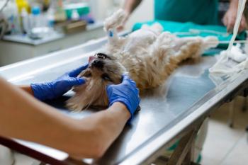
A veterinary technician's guide to emergency ultrasounds
Veterinary technicians, prepare yourself for an ultrasound in action! Heres everything you need to know, from the machine to getting the perfect image from a patientin any situation.
Advertisement
Photos courtesy David Liss, MS, RVT, VTS (ECC, SAIM), CVPM, PHR
Ultrasonography used in a focused manner can be lifesaving in the veterinary emergency room. It lets you identify internal injuries and other problems earlier, which leads to quicker treatment and higher positive outcomes. Fortunately, the movement to train general veterinary practitioners in this modality can be extended to technicians.
Ultrasonography in general often involves assessment and diagnosis, which are outside the scope of practice for a technician. But the actual technical procedure should not be outside a technician's purview. A full-time technician in a practice-especially in situations where relief veterinarians are employed-can assist the veterinarian by performing the ultrasound procedure, and the veterinarian can interpret and diagnose the patient. Let's jump in.
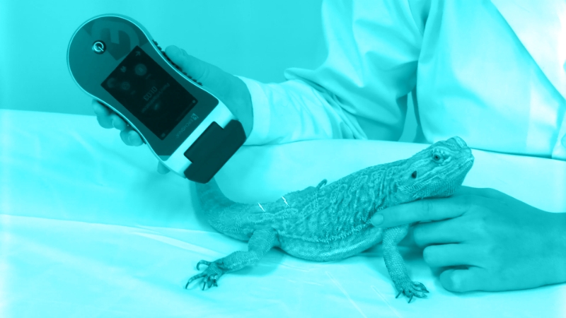
Ultrasound probe.An ultrasound unit consists of two parts: the probe, which transmits and receives the sound wave, and the processor, which interprets the signals and creates an image. The probe contains a crystal that, when stimulated with an electrical signal, vibrates and creates a sound wave. The reverse also occurs, where the sound wave is received by the crystals and they vibrate to create an electrical signal interpreted by the machine. This is termed the “piezoelectric effect.”
Ultrasound processor.
The waves produced by the machine are truly “ultrasonic” at 3 to 14 megahertz (MHz) and therefore too high-pitched to be heard. Sound waves being generated by the probe will enter the body and are subject to a variety of factors that influence their strength, velocity and other factors, which include reflection, refraction, reverberation, attenuation and impedance. Depending on the effects of these factors, the sound wave returning to the probe may vary in quantity, strength and time it takes to echo back to the probe. The machine senses the differences in the returning factors, creates a pixel and ascribes an intensity (called echogenicity) to it.
Important factors to consider
The first important factor to consider is velocity, which is the speed at which the sound wave will travel through a variety of materials. These velocities change depending on the environment. Sound travels at approximately 333 m/sec through air and 4,080 m/sec through bone. Interestingly, sound travels faster through solid objects than gases or liquids. Soft tissue is approximately 1,540 m/sec, with the liver, kidney, blood and muscle ranging between 1,550 to 1,580 m/sec. Most ultrasound machines operate at about 1,540 m/sec.
The second important factor is called acoustic impedance. This is a fairly complicated concept to understand, but it can be simplified in the equation Z = p/v, where Z is acoustic impedance, p is sound pressure (also known as tissue density), and v is velocity. So acoustic impedance is the sound pressure or tissue density divided by the velocity.
Acoustic impedance (AI) is related to amplitude. The amplitude of a wave is related to the difference between the AI between two tissues. Air will have low impedance and bone has high impedance. So if a sound wave comes across a bone-air environment, this will have a large difference in AIs, so a large proportion of sound waves will be reflected. This will create a bright white light on the ultrasound display.
The third factor, absorption, refers to the amount of sound waves absorbed by the tissue being imaged. Scatter, the fourth factor, occurs when some of the ultrasound waves might be scattered due to a variety of angles of the tissue the waves are hitting. This can create distortions on the display.
The reflection of sound waves, the fifth factor, is also important in generating an image. The reflection of the wave will be 90 degrees with a linear probe. This will create a superior image to a curvilinear probe.
Advertisement
The sixth and last factor, attenuation, is the effect of a sound wave losing energy when it travels through tissue. The wave returning to the probe is therefore weaker than it was when it originated. Differences in attenuation also occur at different frequencies, where less attenuation occurs at lower frequencies and more attenuation occurs at higher frequencies. Therefore, more tissue penetration can occur with a lower frequency, but this will result in a lower resolution. Higher frequencies will give better image resolution but consequently receive higher attenuation. So if you want more detail, you'll need a higher frequency-but you'll sacrifice tissue penetration.
Get to know your machine
There are a variety of probes available for ultrasound scanning. The three most common types are phase-array (sector), linear and curvilinear probes. The linear probe is typically higher-frequency and has a square display (also called a footprint) on the monitor. The curvilinear probes are lower-frequency and have a convex face (curved outward). The phase-array probe generates a convex image from a point and is used to get through solid objects like ribs. Probes are often named for their characteristics, e.g. 8C, 9L, 7S, where the number represents the MHz (7, 8 and 9 MHz) and the letter represents the probe type (C for curvilinear, L for linear and S for sector).
Adjustments to the ultrasound image can be made by adjusting four different basic factors on the machine: depth, gain, frequency and focal position or number. Depth is exactly what it sounds like-the depth of the image. The goal is to focus on one area, so the depth should be adjusted to bring the area of interest (the right kidney, for example) directly into the center of the footprint (image). Gain is the brightness of the screen. The rule is not too dark and not too light. The gain knob will adjust the overall brightness, and the time gain compensation (TGC) sliders can adjust the gain across several bands of the image. The brightness should be uniform from top to bottom. If the machine allows frequency adjustment, this can be tweaked as well and can be adjusted slightly to get the ideal resolution and penetration.
Focal position and number can also be adjusted. In short, the more focal points, the greater resolution of the image. However, when more focal points are added, the processor must evaluate more data and will consequently not be able to keep a high frame rate. High frame rates (like a fast camera speed) will create a cleaner image, and low frame rates will make a choppy image; additional focal points slow the frame rate by increasing the data the machine must handle.
Depth, gain, frequency and focal point can all be adjusted to fine-tune the ultrasound image and may need to be adjusted depending on the tissue or anatomy.
Properly receiving (and reading) the image you want
Ultrasound machines have three major modes of operation. The first, B-mode, is two-dimensional and is the most common mode for scanning the abdomen and chest (non-echo). M-mode stands for motion mode, and essentially tracks a set of ultrasound waves over time. This is the mode used for echocardiography and can, for example, measure the various widths inside a ventricle during systole and diastole and can therefore estimate contractility. Color flow doppler mode is used in conjunction with B-mode to see the flow of blood within a vessel and can determine the direction of that flow. Flow is identified as red when it's moving toward the probe and blue when it's moving away. It is most often used in echocardiography to determine if there is any retrograde blood flow across a cardiac valve, thus proving a valvular insufficiency.
The ultrasound image is essentially a mixture of blacks, whites and grays. The image actually represents the opposite of color on a radiograph. As black represents air on a radiograph and white as a pure solid (like bone), the ultrasound image will show air as white and fluid as black.
The image is described in relation to its echogenicity. A variety of terms exist to describe echogenicity. The first, anechoic, is the absence of any sound waves returning to the probe, which shows up as black on an ultrasound image. This represents fluid. The remaining terms describe a tissue in relation to the surrounding tissue. A tissue of interest may be hypoechoic (darker), hyperechoic (brighter) or isoechoic (same brightness) as surrounding tissue. For example, one would say the spleen is hyperechoic (brighter) than the left kidney and the liver is hypoechoic to the spleen. Hypoechoic tissues will be shades of gray. Hyperechoic images will be whites and bright whites.
There are three terms used to describe the directional terms of the ultrasound image. As terms like proximal, distal, lateral and medial represent direction in anatomy or on a radiograph, planes of the body are used to describe the direction of an ultrasound image. Longitudinalimages are parallel to the spine or the long axis of the patient's body. Sagittalimages are long-axis images of a deep structure. Transverseimages occur at a 90-degree angle to the long axis of the structure or tissue in question. Standardizedimage orientation is also essential to ultrasound imaging and interpretation.
When scanning the ventrum (patient is in dorsal recumbency), the longitudinal image projects the ventrum at the top of the screen and the dorsum on the bottom of the screen. Cranial is left, caudal is right. When projecting a transverse image, the ventrum are both on the top and bottom of the image, but the patient's right is on the left side of the screen and the patient's left is on the right side of the screen.
Keeping your wits with any ultrasound
Remember, the patient should have its head facing the machine. However, this isn't always possible in emergency medicine, so a patient might be imaged standing up or from the lateral aspect. In those instances, when scanning a patient laterally (which images the dorsal plane), the longitudinal image shows the nonrecumbent side at the top and the recumbent side on the bottom. Cranial is left and caudal is right. The transverse image is the same except ventral is on the left and dorsal is on the right.
The majority of problems that occur with an ultrasound machine involve the probe. Mistakenly dropping the probe can result in major and sometimes irreparable damage, and probes are costly. Taking care to protect the ultrasound probe can result in major savings. The second-most-common issue with probes is the improper use of alcohol as a conductive fluid. Alcohol can actually damage the probe head. Ultrasound gel should always be used when performing scanning. Proper care of the probe head is vital to proper scanning as probe head damage can result in inefficient generation of sound waves and electrical grounding from the electrical input.
Use of the ultrasound can identify numerous life-threatening conditions and, when performed competently, can be performed rapidly and have high diagnostic utility. Ultrasound is rapidly being integrated as part of the physical exam in human medicine, and veterinary medicine should follow. Technicians can be trained to obtain these images-they can perform the views while the veterinarian reads the images on the monitor and decides on the next diagnostic step.
David Liss, MS, RVT, VTS, CVPM, PHR, is an expert in the areas of veterinary critical care nursing and practice management. He holds a master's degree in biomedical veterinary science and has been a veterinary industry professional for over 17 years. He has worked as a technician in emergency medicine and academia, and he currently manages a 24-hour ER/GP hybrid hospital in Los Angeles. He enjoys the outdoors and time with his chihuahua, Brut.
Suggested reading
1. Boysen SR, Lisciandro GR. The use of ultrasound for dogs and cats in the emergency room: AFAST and TFAST. Vet Clin North Am Small Anim Pract 2013;43:773-797.
2. Boysen SR, Rozanski EA, Tidwell AS, et al. Evaluation of a focused assessment with sonography for trauma protocol to detect free abdominal fluid in dogs involved in motor vehicle accidents. J Am Vet Med Assoc 2004;225:1198-1204.
3. Lisciandro GR. Abdominal and thoracic focused assessment with sonography for trauma, triage, and monitoring in small animals. J Vet Emerg Crit Care 2011;21:104-122.
4. Lisciandro GR. The use of the diaphragmatico-hepatic (DH) views of the abdominal and thoracic focused assessment with sonography for triage (AFAST/TFAST) examinations for the detection of pericardial effusion in 24 dogs (2011-2012). J Vet Emerg Crit Care 2016;26:125-131.
5. Lisciandro GR, Fosgate GT. Use of urinary bladder measurements from a point-of-care cysto-colic ultrasonographic view to estimate urinary bladder volume in dogs and cats. J Vet Emerg Crit Care 2017;27:713-717.
6. Lisciandro GR, Fosgate GT, Fulton RM. Frequency and number of ultrasound lung rockets (B-lines) using a regionally based lung ultrasound examination named vet BLUE (veterinary bedside lung ultrasound exam) in dogs with radiographically normal lung findings. Vet Radiol Ultrasound 2014;55:315-322.
7. Lisciandro GR, Fulton RM, Fosgate GT, et al. Frequency and number of B-lines using a regionally based lung ultrasound examination in cats with radiographically normal lungs compared to cats with left-sided congestive heart failure. J Vet Emerg Crit Care 2017;27:499-505.
8. Lisciandro GR, Lagutchik MS, Mann KA, et al. Evaluation of an abdominal fluid scoring system determined using abdominal focused assessment with sonography for trauma in 101 dogs with motor vehicle trauma. J Vet Emerg Crit Care 2009;19:426-437.
9. McMurray J, Boysen S, Chalhoub S. Focused assessment with sonography in nontraumatized dogs and cats in the emergency and critical care setting. J Vet Emerg Crit Care 2016;26:64-73.
10. Ward JL, Lisciandro GR, Keene BW, et al. Accuracy of point-of-care lung ultrasonography for the diagnosis of cardiogenic pulmonary edema in dogs and cats with acute dyspnea. J Am Vet Med Assoc 2017;250:666-675.
Advertisement
Related Content
Advertisement


Latest CME


Advertisement
Advertisement
Trending on dvm360
1
Tornado (the dog) touches down at the emergency department
2
Every 30 extra minutes under anesthesia raises complication risk in brachycephalic patients, underscoring the importance of peri-anesthetic management
3
Paws and profits: VetEvolve names first chief veterinary officer, NVA appoints two board members, and more updates
4
From the CVO: I’m off the clock
5