Dental instrumentation and maintenance (Proceedings)
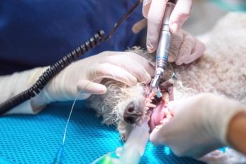
As in human dentistry, veterinary dentistry uses a combination of power and hand instrumentation.
Introduction
As in human dentistry, veterinary dentistry uses a combination of power and hand instrumentation. Periodontal therapy and exodontics are the primary procedures done in the small animal practice. The technician's knowledge of the instruments needed for these procedures is crucial in order to quickly diagnose and treat the dental patient.
Periodontal diagnosis and therapy
The dental chart
The finding of the oral exam of the patient under anesthesia is recorded on the dental chart. The dental chart is a diagrammatic representation of the patient's dentition. Along with the diagram detailed notes need to be made. The dental chart can also be copied and sent home with the owner.
Hand instruments
Parts of the instrument
Handle – The part that you hold in your hand
Shank – This is the segment that connects the handle to the working end
Working End – This is the blade or probe end that touches the tooth. It can be curved or straight. The amount of curve facilitates the use of the instrument in certain areas of the mouth and on certain aspects of the tooth.
Types of hand instruments
Scalers – This instrument has a sharp tip and three sharp edges. The blade can be straight or curved. If you look at the instrument with the tip pointing towards you, it looks like a triangle. It is used only for the removal of supragingival calculus. While there is a myriad of different types of scalers, the most common are the Townsend sickle, the Jacquette, and the Morse.
Curettes – This instrument has one or two sharp edges, a rounded back and a blunt tip or toe. They are used to remove calculus and debris from below the gumline both on the root surface called root planing, and to remove calculus and debris from the opposing surface of the gingival tissue called gingival curettage. The two most commonly used curettes are the Universal (Columbia, Barnhart) which can be used throughout the mouth and the Gracey which has one cutting edge and are area specific. The lower numbers are for incisors and canines and the higher numbers are used on premolars and molars.
Explorers – This instrument is used to examine the tooth surface. It's delicate and flexible steel tip is used to detect any abnormalities using the handlers sense of touch and/or hearing. The most common type of explorer is the Shepherd's hook. There is also a finer tipped explorer when you need more tactile sense to find smaller defects.
Periodontal Probes – This instrument is used to measure the depth of the gingival sulcus or it can measure gingival recession, which ascertains the stage of periodontal disease. Periodontal probes are calibrated in 1-3 mm intervals using notches or color changes.
Power instruments
Ultrasonic power scalers
Magnetorestrictive – This is the most commonly used scaler in practice. The insert fits into a handpiece. The insert is made up of stacked strips of laminated nickel or a ferroceramic rod a.k.a ferromagnetorestrictive. The metal strip insert vibrates causing the tip to move in an elliptical pattern. The ferromagnetorestrictive has a circular tip action. Water cools the tip by flowing into the handpiece and out through the tip. The magnetorestrictive operates at either 25 or 30 kHz. The ferromagnetorestrictive operates at 42 kHz.
Piezoelectric – This scaler has quartz crystals in the handpiece that expand and contract at a constant frequency. The tip has a back and forth motion and oscillates at 45 kHz. The tips screw into a metal base.
Because ultrasonic scalers operate at such a high frequency, they can generate significant heat. Leaving the tip on a tooth for too long or not having a constant water flow can cause thermal damage to the pulp. But when compared to the sonic scalers, the circular motion and the higher frequency decrease the working time.
Sonic scalers
Sonic scalers are usually air driven. The compressed air has a cooling effect and is also irrigated with water at the tip. Because of the presence of the compressed air, they are less likely to cause heat related damage to the teeth that the ultrasonic units can do. The water primarily flushes debris which allows for better visualization. These units operate below 20 kHz and at 30-40 psi of air pressure. The tips for these units also screw into a metal base in the handpiece.
Scaler tips
Tips are available for both the ultrasonic and the sonic scaler for subgingival and supragingival use. The tips do wear down and should be replaced per manufacturer's instructions or sooner depending on use.
Rotary burs
This six sided bur attaches to a high speed handpiece. The bur is used to chip away the calculus by placing the side of the bur against the calculus. This is very technique sensitive and requires a very light touch to avoid removal of the underlying enamel.
Lowspeed handpieces and attachments
Lowspeed handpieces are used primarily in this application for polishing teeth. They run from 5,000 to 20,000 rpm.
Prophy Angle – This attaches to the lowspeed handpiece. A soft rubber prophy cup fits onto the angle either with a screw or snaps directly on to the angle. The prophy cup is filled with prophy paste and the teeth are polished. Thermal damage to the pulp can occur if the prophy cup is left on the tooth too long.
Exodontics
Periosteal Elevator – This instrument is used to elevate the mucoperiosteum in order to facilitate closing the extraction site and/or allow the removal of some of the alveolar bone in a surgical extraction. The larger elevators are used to elevate mucogingival and palatal surgical flaps. The blade comes in different shapes and sizes for use indifferent size patients and types of procedures. The blade has a flat side and a convex side. The flat side goes against the tooth surface while the convex side lies against the soft tissue to reduce tearing and trauma.
Dental Elevator – This instrument is used to stretch cut and tear the periodontal ligament which displaces the tooth root from the socket. The tips have a rounded scoop appearance with a sharp edge which may or may not be serrated. The concave side is placed along the tooth surface while the convex side lies between the tooth and the alveolar bone. The edges come in different sizes and shapes to facilitate different tooth sizes and extraction conditions.
Dental Luxators – This instrument looks like a dental elevator but has a slimmer and in some cases thinner tip design. Their thinner tip allows easier access to the periodontal ligament and is used just to cut the periodontal ligament around the tooth. If you use this instrument like an elevator, there is an increased chance of bending or breaking the tip.
Extraction Forceps - This instrument is used for gripping and removing the tooth after it has been loosened. It can be used for cracking and dislodging heavy dental calculus. The most common type is the small breed forceps which are nicely adapted to the conical shape of the animal tooth. It's small size and spring retraction allows less force to be placed on small teeth reducing the chance of crown fracture.
Root Tip Pick – This instrument is used to stretch and break the periodontal ligament, in order to retrieve a fractured root tip. They can be straight, right angled or left angled and the tips are narrow with two sharps sides and a pointed sharp tip. Gentle pressure must be used to avoid breaking the tip.
Root Tip Forceps – These instruments have fine pointed serrated tips and a 45 degree working angle that allows them to reach deep into the tooth socket to grasp and remove loosened root pieces.
Alveolar Bone Curette – This instrument is used to debride the alveolus after extraction. It has a scoop at the end and can be straight or angled with a long shank to reach deep into the alveolus.
Power instrumentation
Highspeed Handpiece – This instrument is used for sectioning teeth and removing alveolar bone for extractions. It has a water source using compressed air for cooling the bur. Highspeed handpieces run at 300,000 – 400,000 rpm.
Dental Burs - These fit on the highspeed handpiece to section the teeth and remove alveolar bone. For sectioning teeth, a crosscut fissure bur #701 or 701L is used. Round burs are used for slowly removing alveolar bone in a surgical extraction. Round bur sizes range from ¼ to 6 and the size you use depends on the size of the tooth you are working on. Generally, ¼ to 2 is good for cats, 1-3 for small dogs, and 4-6 for large dogs.
Care and maintenance
Sterilization
Because the mouth is not a sterile field, sterilization is used not so much so that you have sterile instruments in a sterile field, but to kill the pathogens left by the previous patient. In the best case scenario, you should have sterilized instruments for each patient, but since most clinics are limited in that respect, you can use cold sterilization between patients, making sure to rinse the instruments thoroughly. At the end of the day, scrub, sharpen (if needed) and sterilize your instruments.
Sharpening and repair
Sharp instruments are necessary to expedite the dental procedure as well as protect the patient from the trauma that can be caused by a dull instrument. Test your instruments by testing them on a sharpening stick or a syringe case. If you have time to sharpen between patients, that's great, but most of the time we get it done when we can. There are many great videos on the market that teach sharpening techniques. These tapes are useful because you can sharpen along with the video. These videos are available through veterinary dental catalogs.
There are also mechanical honing systems available. These can also be used for sharpening other instruments in your hospital. They come with instructional videos and stabilizing guides so that your instruments are at the correct angle. The company that makes this unit is Rx Honing Machine – Mishawaka, IN.
Repairing broken instruments can save you money rather than constantly replacing them. Most major dental suppliers have instrument repair, check into prices and turn around time. These places will also have a sharpening service as well if you want to periodically want to send in your instruments for sharpening.
Equipment manuals and troubleshooting
Routine maintenance of your dental units and handpieces can lengthen the time between major repairs, thereby reducing the stress that comes from equipment breaking down in the middle of a procedure. The equipment manual contains vital information on routine maintenance, troubleshooting, parts, and technical support contacts. Reading and understanding the equipment manual for all of your equipment is important. Keep your equipment manuals and maintenance logs in a central location so that all members of the staff can have access to it. If an equipment manual is not available, I have found the internet a necessary tool, especially with outdated equipment.
Have a backup plan by always having an extra handpiece and parts available in case of a sudden breakdown. The extra parts and handpieces should be in good working order. This will help you troubleshoot and confirm whether the problem is with your handpiece or your dental unit.
Highspeed handpieces — Parts and common problems
Air and Water Inlets/Exhaust – These are the tubes located at the bottom of the handpiece. The configuration can be just the air and water inlet tubes making it a 2-hole handpiece or the above plus two pins making it a 4 holes handpiece. A 4-hole handpiece is the most commonly used. Before ordering a handpiece, make sure the number of holes matches the highspeed fitting on your dental unit.
Spray nozzle - These are the small holes located just below the front of the handpiece head. The water from the dental unit sprays out to cool the tooth. The water outlet lines can become clogged.
Rubber Gasket - On the bottom of the handpiece is a rubber gasket. The gasket helps to seal the handpiece to the fitting so that water and air does not leak. The gasket is usually removable. Replace the gasket when wear or tears start to show.
Head - The chamber on the top of the handpiece where the turbine is housed and spins. With heavy use debris can accumulate inside causing your turbine to stick. Remove the turbine and swab out the head chamber and openings with isopropyl alcohol and lightly spray with oil.
End Cap or Head Cap – Located on the backside of the head of the handpiece. This is where the key of the bur changer is inserted. The end cap is removed using the end cap wrench provided by the handpiece manufacturer. You should get one of these with your handpiece. If you don't have a wrench that fits, contact the manufacturer for part information. The end cap can also become stripped and should be replaced.
Bur Changer – The key that is used to loosen or tighten the bur into the handpiece. The changer fits over the head of the handpiece and a spring is pulled back and the key is inserted into the back end of the head. Turn counter clockwise to loosen and clockwise to tighten. With time the edges of the key will become dull and the bur changer will need to be replaced. The bur changer should be cleaned and lubricated like the rest of you instruments.
Chuck – This is what the bur is inserted into. The chuck is located inside the turbine. A common failure of this part is caused by over tightening the bur. Overtightening can strip your chuck and dull the edges on your bur changer. A good rule of thumb is to count the number of turns you made to loosen the chuck and then retighten with the same number of turns. Two turns will usually do the trick. Once tightened, carefully and gently pull on the bur (keep your feet away from the dental unit pedal) to make sure the fit is snug.
When you have a stripped chuck, the bur changer will not tighten, it will keep spinning. First try tighten the bur with another bur changer to make sure the bur changer isn't rounded off. The chuck can be removed by removing the end cap, insert the bur changer key directly into the back of the turbine. The chuck will back out as you loosen. Remove the stripped chuck and replace it with a new one and tighten it back up and replace the end cap.
Turbine – The part that spins the bur. When removing the turbine for maintenance, replace the bur with a "blank" bur. Unscrew and remove the end cap, then push down on the blank on a hard surface till the turbine pops out. Replace the turbine by putting the turbine blank first into the back of the handpiece. There is a knob pin on the back edge of the turbine. This pin needs to be aligned with the groove on the top edge of the back of the head chamber. When purchasing a new turbine, it is best to use the turbine made for your handpiece. Call the handpiece manufacturer for information. Keep extra turbines and chucks in case of intraoperative breakdown.
Signs of a stripped turbine - The bur changer will not open the chuck. If you look at the front of the handpiece, the nut that the bur slides into will be sticking out farther than normal. This occurs when you put too much downward pressure on the bur. Another sign of a stripped turbine is seen when your bur stops spinning intermittently or altogether.
Routine highspeed handpiece maintenance
Daily - Lubricate your handpieces daily. Remove the handpiece from the unit. Look at the bottom of the handpiece. Rotate the tiny pins at the bottom of the handpiece till they are in the 6:00 position. There will be one or two larger holes above the pins. If there is one, place 2-3 drops of lubricating oil or spray into this hole. If there are 2 holes, place the lubricant in the smaller of the 2 holes which is usually the one on the right in the 3:00 position.
Weekly - Remove the turbine from the handpiece. Clean the inside of the head chamber with isopropyl alcohol then spray lightly with aerosol lubricant. Then place 2-3 drops of lubricating oil into the opening in the side of the turbine. Replace the turbine in the handpiece.
Insert a fine gauge wire into the spray nozzle holes and move it back and forth to loosen the debris. Run the handpiece for 2 minutes to loosen debris and distribute the oil.
Lowspeed handpieces
Parts
Nose Cone - This is the removable part of the handpiece. This is the part that houses the motor. There are generally 2 speeds. The slow speed motor which is used mainly for polishing or endodontics, runs anywhere up to 5500 rpm, depending on the manufacturer. The high speed motor runs anywhere from 20,000 22,000 rpm, depending on the manufacturer and is used with finishing or trimming burs. Check the manufacturer's instructions for the attachment or bur that you are using to know what speed would be best.
Chuck Housing Ring - This is located on the nose cone and usually locks and unlocks the handpiece to allow the placement or removal of the prophy angle or contra angle or handpiece (HP) bur. To open the handpiece, depress the housing ring by pressing it towards the bottom of the handpiece while twisting it ¼ turn clockwise. Relock the handpiece by twisting the housing ring ¼ turn counterclockwise.
Forward/Reverse Speed Direction Ring - This is located at the bottom of the handpiece. It is used to change the direction of the rotation to either forward or reverse. It also controls the speed of the handpiece. To make the angle move forward, rotate the ring on the handpiece clockwise. To make the angle rotate in a reverse direction, rotate the direction ring in a counterclockwise direction. The middle position stops the handpiece. The more the ring is rotated away from the middle position, the faster the operating speed.
Routine lowspeed handpiece maintenance
Daily - Clean the outside of your handpiece by carefully washing and rinsing with hot water. Apply a non abrasive disinfectant cleanser to the outside of the handpiece, scrub and rinse. Dry the handpiece using a clean dry towel.
Lubricate your handpiece daily. Remove the handpiece from the unit. Look at the bottom of the handpiece. On most handpieces, there will be 4 holes – 2 tiny and two larger. Rotate the handpiece till the tiny pins are in the 6:00 position. Look at the larger holes; place 2-3 drops of oil in the smaller of the two holes which is usually on the right, known as the air inlet. Run the handpiece for 5-10 seconds to distribute the oil to all internal parts.
Weekly - The nose cone, the chuck housing ring, and the speed direction ring need to be lubricated
Sterilizing your handpieces
Check with the manufacturer of your handpiece regarding specific instructions for your handpiece. These are general guidelines for autoclaving.
Highspeed Handpiece - Before autoclaving your highspeed handpiece, make sure the turbine is autoclavable. After you thoroughly clean the handpiece, remove the turbine; clean it and the head cavity the turbine sits in. Any debris left will be scorched by the autoclave and cause damage to the turbine.
Insert a few drops of oil through the openings in the side of the turbine housing. Put the turbine back into the handpiece. Put the handpiece in a sterilization peel pack. Sterilize at a maximum temperature of 275° F.
Lowspeed Handpiece - After you thoroughly clean the handpiece, insert a few drops of oil in the air inlet hole at the bottom of the handpiece (see cleaning instructions mentioned earlier in this paper).
Remove the nose cone and oil both ends. Lubricate the gear shaft on the handpiece. After lubricating assemble and operate for a few seconds to dispel any excess lubricant.
Put the handpiece in a sterilization peel pack. Sterilize at a temperature of 275° F for at least 20 minutes. Relubricate the handpiece as previously instructed.
Handpiece attachments
Contra angles
Immerse the working end of the instrument in a lubricant bath. Run the instrument for a minute or two. This will remove any grit and debris.
Prophy angle
Sealed – Remove the prophy cup from the head. For the screw type, supply 2-3 drops of oil into the rotor shaft at the tip. For the snap-on type, supply 2-3 drops into the hole in the center of the snap-on knob.
Unsealed – Unscrew the head by turning it counterclockwise. Spray and clean the gears using a lubricant spray. Lubricate the gears with 1-2 drops of oil. Replace the head by screwing it back on clockwise. Remove the head cap using the supplied wrench by turning it clockwise. Spray and clean the gears using a lubricant spray. Lubricate the gears with 1 drop of oil. Replace the cap by turning the cap counterclockwise.
Autoclaving – Most metal prophy angles can be autoclaved at 275°F.
Dental unit maintenance
Dental units can be driven by an air compressor or by nitrogen gas.
Check with the manufacturer of your dental unit for maintenance instructions specific to your dental unit. These are just a few general guidelines.
Air compressors
Air Storage Tank - Condensation will build up inside the tank. Depending on the amount of humidity in your area, the condensation will need to be drained weekly to monthly. The drain valve is located either on the top or bottom of the air storage tank. Turn off the dental unit. With pressure remaining in the tanks, open the drain valve to remove the condensation. Keep the valve open until the pressure gauge reads "zero". Wipe the tank clean.
Moisture Trap Filter - Some units will have a secondary trap for condensation. There is a pin at the bottom that you depress to bleed condensation and moisture. This is done weekly or monthly depending on humidity levels. Do this with the unit turned off and pressure still in the tanks. Depress the pin until the pressure gauge reads "zero".
Oil Tank - An oil level indicator or dipstick is attached to the compressor tank. The level and the color of the oil should be checked monthly. Some compressors will have you change the oil annually.
Nitrogen driven
Read the manufacturer's instructions to know where to set the "psi" on the tank gauge for the dental unit. The nitrogen needs to be bled out of the lines after each day of use. Turn off the nitrogen on the main knob. Bleed out the lines by running one of the handpieces continuously until the pressure gauge reads "zero". Open or loosen the pressure regulator.
When to call in the experts?
ASK FOR HELP from the professionals when the repair need goes beyond your expertise and your phone conversations with technical support. Many towns and cities have medical equipment repair services. Your local dentist or hospital can sometimes be helpful with recommendations. If they have to come to your practice, you will usually have to pay a trip fee along with the cost of parts. Final tip – ask if you can watch them work. You can learn a lot and possibly be able to handle the problem in-house next time.
References
Bellows J: Equipping your dental practice, in The Practice of Veterinary Dentistry: A Team Approach. Ames, Iowa State University Press, 1999, 45-58.
Holmstrom SE, Fitch PF, Eisner ER: Dental Equipment and Care, in Veterinary Dental Techniques for the Small Animal Practitioner, Third Edition. Philadelphia, Saunders, 2004, pp 48-51.
Holmstrom SE: Dental instruments and equipment, in Veterinary Dentistry for the Technician and Office Staff. Philadelphia, WB Saunders, 2000, pp 65-84.
Lobprise HB, Wiggs RB: Materials and equipment, in The Veterinarian's Companion for Common Dental Procedures. Lakewood, AAHA Press, 2000, pp 166-168.
Newsletter
From exam room tips to practice management insights, get trusted veterinary news delivered straight to your inbox—subscribe to dvm360.


